Counter ICs, or counter integrated circuits, are a type of digital logic IC (integrated circuit) that is designed to count the number of input pulses or a specific event occurrence. These ICs are used in various digital electronic applications where there is a need to keep track of events, generate timing signals, or divide frequencies.
Here are some key points about counter ICs:
-
Counting Function: Counter ICs consist of a series of flip-flops or other counting elements that increment or decrement a binary number based on input clock pulses. These ICs can count up, count down, or count in other sequences based on their design.
-
Applications:
- Frequency division: They are commonly used to divide the frequency of clock signals.
- Event counting: They can count the occurrence of events or pulses.
- Timing and sequencing: Counter ICs are used in various timing and sequencing applications in digital systems.
-
Types of Counters:
- Asynchronous Counters: These counters do not share a common clock signal for all stages and may have different clock inputs for different stages.
- Synchronous Counters: These counters share a common clock signal and have all flip-flops or counter stages connected to the same clock signal.
- Binary Counters: These counters increment or decrement in binary sequences.
- Decade Counters: These counters represent numbers in decimal form, typically counting from 0 to 9 before rolling over.
- Up Counters and Down Counters: Up counters increment the count on each clock pulse, while down counters decrement the count.
-
Cascade Connection: In applications where higher counting ranges are needed, multiple counter ICs can be cascaded together to create a larger counting range.
-
Decoding and Outputs: Counter ICs may have additional features like decoded outputs, which can be used to trigger other logic functions based on specific count values.
-
Frequency Dividers: Some counter ICs are primarily used as frequency dividers, dividing an input frequency by a constant factor to produce a lower frequency output.
Counter ICs play a crucial role in digital circuit design for tasks such as event counting, frequency division, clock generation, and timekeeping. They provide a fundamental building block for creating various digital systems and are commonly found in applications ranging from simple digital clocks to complex microprocessor-based systems.
What are the Types of Counter ICs?
Counter ICs come in various types to suit different counting and sequencing requirements in digital circuit designs. Some common types of counter ICs include:
-
Ripple Counters:
- These counters use cascaded flip-flops with the output of one flip-flop connected to the clock input of the next flip-flop.
- They are simple to implement but can suffer from limitations such as propagation delays affecting the overall timing accuracy.
-
Synchronous Counters:
- In synchronous counters, all the flip-flops receive the same clock signal simultaneously.
- They offer advantages in terms of better timing accuracy and reduced propagation delays compared to ripple counters.
-
Decade Counters:
- Decade counters are designed to count from 0 to 9 in decimal form before resetting back to 0.
- They are commonly used for applications where a count needs to be displayed in decimal format.
-
Up/Down Counters:
- Up counters increment the count with each clock pulse.
- Down counters decrement the count with each clock pulse.
- Some counter ICs can function as both up and down counters based on the control inputs provided.
-
Johnson Counters (Twisted Ring Counters):
- Johnson counters have a circular shift register topology and provide a non-binary count sequence.
- The outputs of these counters produce a sequence that repeats after a particular number of states.
-
Binary Counters:
- Binary counters increment the count in binary form.
- They are commonly used for various counting and sequencing tasks in digital circuits.
-
Modulus Counters:
- Modulus counters are presettable counters that can be programmed to count up to a specific value before resetting.
- They allow for flexible counting operations based on the desired modulus value.
-
BCD Counters (Binary-Coded Decimal Counters):
- BCD counters count in Binary Coded Decimal format, counting from 0 to 9 before resetting to 0.
- These counters are useful for applications involving BCD data representation.
-
Ring Counters:
- Ring counters are circular shift registers where only one flip-flop is active at a time.
- They offer a simple form of sequence generation in digital circuits.
These are some of the common types of counter ICs used in digital electronics for various counting, sequencing, and timing applications. Each type of counter IC has its own characteristics and is chosen based on the specific requirements of a given digital design.
What is the Counter IC used for?
Counter ICs are widely used in digital electronics for a variety of counting, sequencing, and timing applications. Here are some common uses of counter ICs:
-
Frequency Division:
- Counter ICs are frequently used to divide the frequency of clock signals. By counting a specific number of input clock pulses, the counter can generate an output signal with a lower frequency.
-
Event Counting:
- Counter ICs are used to count the occurrence of external events or pulses. They keep track of the number of input events and provide a binary or decoded output representing the count.
-
Timing and Sequencing:
- Counter ICs are utilized in applications where precise timing and sequencing of events are required. They help generate timing signals for synchronizing various operations within a digital system.
-
Frequency Generation:
- By utilizing specific count sequences, counter ICs can be used to generate various frequencies for applications such as clock generation, signal processing, and waveform generation.
-
Digital Clocks and Timers:
- Counter ICs are used in digital clocks, timers, and chronometers to keep track of time by counting clock pulses. They form the fundamental building blocks of timekeeping circuits.
-
Address Generation:
- In microcontrollers and memory systems, counter ICs are employed to generate memory addresses and facilitate data retrieval and storage operations.
-
Control and Sequence Logic:
- Counter ICs help in implementing control and sequence logic in digital systems. They enable the generation of specific sequences of states based on the counting operations.
-
Automated Systems:
- In automation and control systems, counter ICs are used for tasks such as counting input signals from sensors, monitoring operational cycles, and controlling sequential processes.
-
Data Processing:
- Counter ICs play a role in data processing tasks where counting and sequencing operations are required to manipulate and process digital data efficiently.
-
LED and Display Drivers:
- In applications where LED or display panels need to be illuminated in a specific sequence, counter ICs are used to control the scanning or multiplexing of display elements.
Counter ICs are essential components in digital systems, providing the capability to count events, generate timing signals, sequence operations, and perform various other counting-related tasks. Their versatility and functionality make them indispensable in a wide range of electronic applications, from simple timers and counters to complex digital systems requiring precise control and synchronization.
How does Counter IC Work?
Counter ICs operate based on the principles of sequential logic, utilizing flip-flops or other internal elements to count input pulses or events. The operation of a counter IC can vary depending on its design and type, but the fundamental working principle involves the following key aspects:
-
Input Clock Signal:
- A counter IC typically has an input pin for a clock signal. This clock signal drives the counting operation of the counter. Every rising or falling edge of the clock signal triggers the counter to increment or decrement its count.
-
Internal Counting Elements:
- Counter ICs consist of flip-flops or other types of sequential logic elements arranged in a specific configuration to form a counter. Each flip-flop represents a binary stage in the counter.
-
Counting Sequence:
- When the counter receives a clock pulse, the internal logic of the counter determines whether to increase the count, decrease the count, or stay in the current state based on the design of the counter IC.
- Different types of counters have specific counting sequences, such as binary counting, decade counting, up/down counting, or other customized sequences.
-
Cascade Connection:
- For counters with a higher counting range, multiple stages of flip-flops are cascaded together. The output of one stage is connected to the clock input of the next stage, allowing for a larger counting range.
-
State Transitions:
- As the counter increments or decrements based on clock pulses, it transitions through different states, with each state representing a specific count value.
- The outputs of the counter IC reflect the current count value in binary or decoded form.
-
Reset and Control Inputs:
- Counter ICs often feature control inputs for functions such as resetting the count to a specific value, enabling or disabling counting, and configuring the direction of counting (up or down).
-
Output Signals:
- The output signals of the counter IC provide the current count information. These outputs can be in binary form (individual outputs for each bit) or decoded (binary-to-decimal conversion).
-
Overflow and Carry Outputs:
- In multi-bit counters, overflow or carry outputs can indicate when the counter has reached its maximum count value and is about to roll over to 0 or a predetermined value.
-
Applications of the Count:
- The count generated by the counter IC can be utilized for various purposes, such as triggering other logic elements, controlling external devices, generating timing signals, addressing memory locations, or sequencing operations in a digital system.
Overall, the functionality of a counter IC is based on its internal logic design, clock input signals, state transitions, and control inputs. By manipulating these aspects, counter ICs can perform a wide range of counting and sequencing tasks essential for digital electronics applications.
What are the Benefits of Using Counter ICs?
Using counter ICs offers several advantages in digital electronics design and implementation. Some key benefits of using counter ICs include:
-
Counting Functionality: Counter ICs provide a convenient and efficient way to count events, pulses, or clock cycles in digital systems. They automate the counting process and enable accurate tracking of occurrences.
-
Timing and Synchronization: Counter ICs are crucial for generating timing signals and synchronizing different elements within a digital system. They ensure that operations occur in a coordinated and orderly manner.
-
Frequency Division: Counter ICs are commonly used for frequency division tasks, allowing designers to scale down the frequency of clock signals to drive various components at different speeds.
-
Control and Sequencing: Counter ICs facilitate the implementation of control and sequencing logic in digital circuits. They enable the generation of specific sequences of states or events based on counting operations.
-
Address Generation: In microcontroller-based systems and memory applications, counter ICs are utilized for address generation, enabling efficient data access and storage.
-
Versatility: Counter ICs come in various types, such as up counters, down counters, synchronous counters, asynchronous counters, and more. This versatility allows designers to choose the most suitable type for a particular application.
-
Integration: Counter ICs are available as integrated circuits, which makes them easy to incorporate into designs. They simplify the overall circuit complexity by providing a dedicated counting solution in a single chip.
-
Reliability: Counter ICs are designed to operate reliably in digital systems, offering stable and predictable counting behavior. They are manufactured to meet specific performance criteria and standards.
-
Efficiency: Using counter ICs can enhance the efficiency of digital circuits by offloading counting and sequencing tasks from the main microcontroller or processor, thus optimizing system performance.
-
Cost-Effectiveness: Counter ICs are cost-effective solutions for implementing counting and timing functionalities in digital designs. They reduce the need for complex discrete logic circuits, saving both component costs and board space.
-
Scalability: Counter ICs can be easily cascaded together to create counters with larger counting ranges. This scalability feature allows for flexibility in designing systems with different counting requirements.
Overall, the benefits of using counter ICs include enhanced functionality, precise timing capabilities, ease of integration, reliability, and cost-effectiveness. These advantages make counter ICs essential components in a wide range of digital systems and electronic applications.
What are the Limitations of using Counter IC?
While counter ICs offer many advantages for counting, sequencing, and timing applications in digital electronics, they also have some limitations that designers should consider:
-
Limited Counting Range: One of the primary limitations of counter ICs is their finite counting range. Depending on the number of bits in the counter, there is a maximum count value that the counter can reach before rolling over to 0. Designers must ensure that the selected counter IC can accommodate the required counting range for a specific application.
-
Propagation Delay: In asynchronous counters, each flip-flop stage introduces a certain amount of propagation delay. As the count propagates through the stages, this delay accumulates, potentially impacting the overall timing performance of the system.
-
Clock Skew: Clock skew can affect the operation of synchronous counters, especially in applications where multiple counters are cascaded together. Skew refers to the difference in arrival times of clock signals at different parts of the circuit, which can lead to timing errors and signal integrity issues.
-
Synchronous Design Challenges: Designing synchronous counters requires careful consideration of clock signal distribution, setup and hold times, and clock edge synchronization. Ensuring proper timing and signal integrity can be challenging in complex synchronous counter designs.
-
Power Consumption: Counter ICs, especially those with multiple stages, can consume significant power, especially in high-speed applications where clock frequencies are high. Power consumption is an important consideration in battery-powered or energy-efficient designs.
-
Complexity: Designing and debugging complex counter circuits, especially those with multiple modes of operation or specialized features, can be challenging. Increasing the complexity of the counter design can lead to higher chances of errors and longer development times.
-
Limited Functionality: While counter ICs are designed for counting operations, they may not offer additional features or advanced functions that are required in some applications. Designers may need to supplement counter ICs with other components to achieve specific requirements.
-
Glitches and Race Conditions: In asynchronous counters or improperly designed synchronous counters, glitches and race conditions can occur, leading to unpredictable behavior or incorrect count values. Proper circuit design and consideration of timing constraints are essential to mitigate these issues.
-
Testing and Verification: Verifying the correct operation of counter ICs, especially in complex circuits, can be challenging. Thorough testing and simulation are necessary to ensure that the counter functions as expected under various operating conditions.
-
Cost: While counter ICs are generally cost-effective solutions, advanced or specialized counter ICs with specific features may come at a higher cost. Balancing the cost with the required functionality is important in the design process.
Despite these limitations, counter ICs remain essential components in digital electronics, offering a convenient and efficient way to implement counting and timing functions in a wide range of applications. By understanding and addressing these limitations, designers can effectively integrate counter ICs into their designs while minimizing potential challenges.
What Factors are Considered When Classifying IC Counters?
When classifying IC counters, various factors are taken into account to categorize them based on their characteristics, functionality, and design. Some of the key factors considered when classifying IC counters include:
-
Counting Direction:
- Counters can be classified based on their counting direction, which includes up counters (counting incrementally), down counters (counting decrementally), and up/down counters (counting in both directions).
-
Counting Sequence:
- The counting sequence can vary among counters. Some counters follow a binary counting sequence, while others may have a decimal (BCD) counting sequence, Gray code sequence, or other custom sequences.
-
Modulus:
- Modulus refers to the maximum count value before the counter resets. Counters can be classified based on their modulus, such as modulus-N counters that count up to N before resetting.
-
Synchronous vs. Asynchronous:
- Counters can be categorized as synchronous or asynchronous based on how they handle clock signals. Synchronous counters use a common clock signal for all stages, while asynchronous counters propagate count based on individual clock inputs.
-
Decade Counters:
- These counters are designed to count from 0 to 9 and then reset. They are commonly used in applications where decimal counting is required.
-
Parallel vs. Serial:
- Counters can be parallel or serial depending on how data is loaded and shifted through the counter stages. Parallel counters load all bits simultaneously, whereas serial counters shift data bit-by-bit.
-
Ring Counters vs. Johnson Counters:
- Ring counters and Johnson counters are special types of counters with unique characteristics. Ring counters have a rotating 1-bit pattern, while Johnson counters produce a non-sequential output sequence.
-
Presettable Counters:
- Presettable counters allow users to load an initial value into the counter, enabling them to start counting from a specific value rather than from 0.
-
Frequency Division:
- Some counters are specifically designed for frequency division applications, dividing an input frequency to a lower output frequency based on a specific counting sequence.
-
Special Features:
- Counters may have additional features such as ripple carry outputs, ripple borrow outputs, synchronous load inputs, asynchronous clear inputs, and enable or direction control inputs. These features can influence how counters are classified.
By considering these factors and the specific characteristics of a counter IC, designers can classify counters into different types based on their operational modes, counting capabilities, counting sequences, and additional functionalities. Understanding these classification criteria helps in selecting the most suitable counter IC for a given application and designing digital circuits with the required counting and sequencing capabilities.
What Distinguishes Asynchronous from Ripple Counters?
Asynchronous counters and ripple counters are similar in the sense that they both utilize cascaded flip-flops to count input pulses. However, there are key differences between the two types of counters that distinguish them in terms of their operation and performance:
-
Clock Signal Handling:
- Ripple Counters: Ripple counters have a ripple effect when clock signals propagate through the stages. Each flip-flop in a ripple counter triggers the next flip-flop asynchronously, causing a delay between each stage of the counter. This sequential triggering leads to potential timing issues and introduces propagation delays.
- Asynchronous Counters: Asynchronous counters also employ cascaded flip-flops, but they are designed in such a way that all flip-flops receive the same clock signal simultaneously. This synchronous clocking ensures that all stages change state at the same time, reducing propagation delays and improving timing accuracy.
-
Timing and Propagation Delays:
- Ripple Counters: Due to the ripple effect of clock signals in ripple counters, there can be significant propagation delays between stages. This can result in timing skew issues and limit the maximum clock frequency at which the counter can reliably operate.
- Asynchronous Counters: Asynchronous counters generally have better timing characteristics compared to ripple counters because all flip-flops change state simultaneously in response to the clock signal. This synchronous operation helps to minimize propagation delay issues and improve timing accuracy.
-
Complexity and Design Considerations:
- Ripple Counters: Ripple counters are relatively simple to design and implement, making them suitable for basic counting applications. However, their asynchronous operation can lead to timing challenges in more complex or high-speed applications.
- Asynchronous Counters: Asynchronous counters are more sophisticated in terms of design, requiring careful consideration of clock signal distribution and synchronization. While they offer better timing characteristics than ripple counters, they may be more complex to implement in certain scenarios.
-
Speed and Frequency Operation:
- Ripple Counters: Ripple counters are typically slower in operation compared to asynchronous counters due to the cascaded ripple effect that introduces delays between stages. This limitation can restrict the maximum clock frequency at which the counter can reliably function.
- Asynchronous Counters: Asynchronous counters are better suited for high-speed applications because of their synchronous operation, which helps minimize propagation delays and allows for faster counting operations at higher clock frequencies.
In summary, the primary distinction between asynchronous and ripple counters lies in their handling of clock signals and timing characteristics. Asynchronous counters provide synchronous clocking to all stages, resulting in improved timing accuracy and reduced propagation delays compared to the asynchronous ripple effect seen in ripple counters. Designers must carefully evaluate the requirements of their specific applications to determine whether an asynchronous or ripple counter is the most suitable choice for a given counting task.
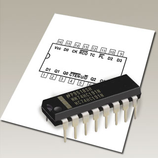
What is a 74LS193 Four-Bit Binary Counter?
The 74LS193 is a popular integrated circuit (IC) that functions as a synchronous 4-bit binary up/down counter. This IC is part of the 74LS family of TTL (Transistor-Transistor Logic) devices and is widely used in digital electronics for counting and sequencing applications. Here are some key features and characteristics of the 74LS193 four-bit binary counter:
-
Functionality:
- The 74LS193 IC is a 4-bit synchronous binary counter with both up and down counting capabilities. It can count in either direction based on the control inputs provided.
- The counter can be preset to an initial value using the Parallel Load (PL) inputs, allowing for flexibility in the starting count value.
-
Counting Modes:
- The 74LS193 IC supports both up-counting and down-counting modes, which can be controlled using the Up/Down (U/D) input pin.
- When the U/D input is HIGH, the counter increments (up-counts), and when the U/D input is LOW, the counter decrements (down-counts).
-
Synchronous Operation:
- This IC operates synchronously, meaning that all flip-flops within the counter change state simultaneously in response to the clock signal, ensuring accurate and synchronized counting.
-
Parallel Load Feature:
- The 74LS193 includes Parallel Load (PL) inputs that allow the counter to be loaded with an initial count value directly. This feature enables the counter to start counting from a specific preset value rather than from 0.
-
Carry/Borrow Output:
- The IC provides a Carry/Borrow output (Cn) that indicates when the count reaches its maximum value in up-counting mode or when borrowing occurs in down-counting mode.
-
Reset Capability:
- The 74LS193 IC typically includes a synchronous clear (CLR) input that allows the counter to be reset to a specific initial state or count value as needed.
-
Power Supply Voltage:
- The 74LS193 operates within a specified range of power supply voltages, typically around 5 volts DC.
-
Package Type:
- The 74LS193 IC is available in different package types such as DIP (Dual Inline Package) and may contain four flip-flops within the IC package to create the 4-bit counter.
Overall, the 74LS193 four-bit binary counter is a versatile and widely used IC in digital electronics for various counting and sequencing applications. Its synchronous operation, dual up/down counting modes, preset capability, and other features make it a valuable component in digital circuit design where precise and flexible counting functionality is required.
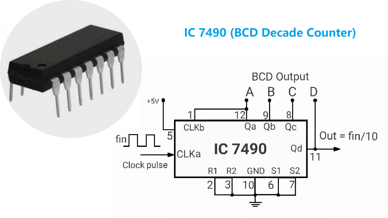
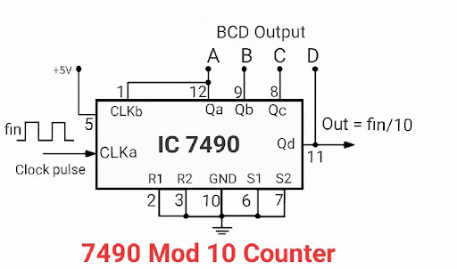
What is a 74LS90 Decade Counter?
The 74LS90 is a decade counter IC (Integrated Circuit) that is widely used in digital electronics for counting purposes. Specifically, the 74LS90 is a 4-bit ripple counter designed to count in decimal (0-9) sequences. Here are some key features and characteristics of the 74LS90 decade counter:
- Decade Counting:
- The 74LS90 IC is designed to count in decade (0 to 9) sequences. It can progress through the decimal numbers from 0 to 9 and then reset back to 0.
- Ripple Counter:
- The 74LS90 is a ripple counter, meaning that the internal flip-flops are connected in a cascaded manner, with each flip-flop triggering the next one, causing a ripple effect when counting.
- Asynchronous Counting:
- In the 74LS90, each flip-flop operates asynchronously, with the output of one flip-flop triggering the next flip-flop without requiring a common clock signal for all stages.
- Reset Functionality:
- The 74LS90 typically includes a reset input that allows the counter to be cleared and reset to 0 manually, enabling control over the initial count state.
- Binary Coded Decimal (BCD) Output:
- The outputs of the 74LS90 represent the current count value in binary coded decimal (BCD) form, with separate lines for each digit (0-9).
- Clock Signal Input:
- The 74LS90 requires a clock signal input to increment the count. Each rising or falling edge of the clock signal causes the counter to advance to the next count value.
- Output Carry Signal:
- The 74LS90 may have an output carry signal that toggles high when the counter completes a full decade count from 0 to 9, indicating that the counter is about to reset.
- Power Supply Voltage:
- The 74LS90 operates within specific voltage ranges, usually around 5 volts DC in standard TTL logic circuits.
- Package Type:
- The 74LS90 IC is commonly available in Dual Inline Package (DIP) form, which is a widely used package type for ICs.
The 74LS90 decade counter is a fundamental building block in digital logic circuits, providing reliable counting capabilities for applications that require sequential counting in decimal form. Its simplicity and ease of use make it a popular choice for various digital electronics projects where decade counting is essential.
Which Integrated Circuit Counter Should I Choose?
Choosing the right integrated circuit (IC) counter depends on several factors, including your specific requirements, the features needed for your project, and the complexity of the counting task. Here are some considerations to help you choose the appropriate IC counter for your application:
-
Counting Range:
- Determine the range of counts required for your project. Some counters are designed for decade counting (0-9), while others can count over a larger range of values.
-
Direction of Counting:
- Decide whether you need a counter that counts up, down, or both (up/down counter) based on the requirements of your application.
-
Counting Sequence:
- Consider whether you need a binary counter, BCD counter, or a counter with a specific counting sequence based on the nature of your project.
-
Clock Frequency:
- Look at the maximum clock frequency that the counter IC can handle to ensure it fits within the requirements of your system.
-
Synchronous vs. Asynchronous:
- Determine whether a synchronous or asynchronous counter is more suitable for your design based on timing and synchronization needs.
-
Additional Features:
- Consider any special features you may require, such as preset inputs, clear inputs, carry outputs, ripple carry functionality, or other specific capabilities.
-
Package Type:
- Decide on the package type that would be most suitable for your project, such as Dual Inline Package (DIP), surface-mount packages, or specialized packages.
-
Power Supply Voltage:
- Ensure that the IC counter operates within the voltage range of your system to prevent compatibility issues and potential damage.
-
Cost and Availability:
- Consider the cost of the IC counter and its availability from suppliers to ensure that it fits within your budget and timeline constraints.
-
Datasheet Analysis:
- Review the datasheets of potential IC counters to understand their specifications, performance characteristics, and recommended application circuits.
Some commonly used IC counters include the 74HCXXX series, 74LSXXX series, and 4000 series CMOS counters. The specific model you choose will depend on the factors outlined above as well as your project's unique requirements. It's essential to carefully evaluate these factors to select the most suitable IC counter that meets your design objectives and specifications.
How can You Define High-Quality Counter IC?
Defining a high-quality counter IC involves considering several key characteristics and specifications that contribute to its performance, reliability, and suitability for various applications. Here are some criteria that can help define a high-quality counter IC:
-
Accuracy: A high-quality counter IC should provide accurate counting and timing functionality, ensuring precise and reliable operation in digital systems.
-
Frequency Range: The IC should support a wide range of input clock frequencies while maintaining consistent performance across different frequency ranges.
-
Counting Range: The counter IC should offer a counting range suitable for the intended application, whether it involves low counts, high counts, or specific counting sequences.
-
Counting Direction: The IC should support the required counting direction (up, down, or up/down) based on the application's needs.
-
Minimal Jitter: A high-quality counter IC should have low jitter to ensure stable and consistent timing behavior, especially in timing-critical applications.
-
Fast Response Time: The IC should have a fast response time to input clock signals to enable rapid counting and response to events.
-
Low Power Consumption: Energy efficiency is crucial, and a high-quality counter IC should consume low power to minimize energy usage and heat dissipation.
-
Noise Immunity: The IC should exhibit good noise immunity to prevent errors or miscounts caused by external electrical noise or interference.
-
Output Drive Strength: The IC should have robust output drivers to ensure reliable signal transmission to connected components or devices.
-
Temperature Stability: A high-quality counter IC should exhibit stable performance across a wide temperature range to maintain accuracy and reliability in various operating conditions.
-
Data Integrity: The IC should maintain data integrity throughout the counting process, ensuring that counts are not lost or corrupted during operation.
-
Ease of Integration: The IC should be easy to integrate into circuit designs, with clear documentation, standard pin configurations, and compatibility with common digital logic levels.
-
Reliability and Longevity: A high-quality counter IC should be durable and reliable, with a long operational lifespan to ensure consistent performance over time.
-
Comprehensive Datasheet: The datasheet for the counter IC should provide detailed specifications, application notes, timing diagrams, and other essential information to facilitate design and integration.
By evaluating a counter IC based on these criteria, you can determine whether it meets the standards of a high-quality component that can effectively address the requirements of your digital system design and deliver reliable counting and timing functionality.