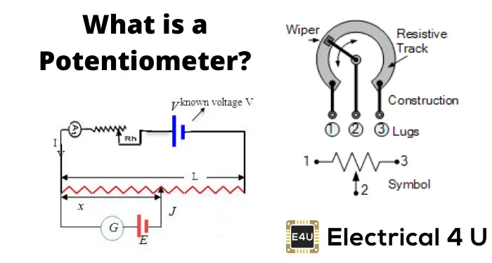
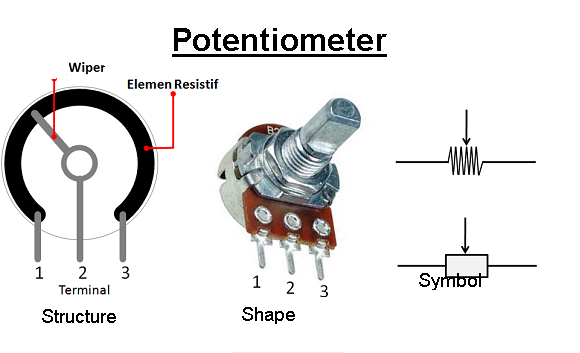
A potentiometer is a three-terminal variable resistor that allows you to manually adjust the resistance in a circuit. It consists of a resistive track with a sliding contact (wiper) that can be moved to change the resistance value. Here are some key points about potentiometers:
Components of a Potentiometer:
- Resistive Track: A strip of resistive material that determines the overall resistance value of the potentiometer.
- Wiper: A movable contact that slides along the resistive track, creating an adjustable voltage divider.
- Terminals: Three terminals—two outer terminals connected to each end of the resistive track and a middle terminal connected to the wiper.
Types of Potentiometers:
- Linear Potentiometer: The resistance value changes linearly with the position of the wiper. Used for applications where a linear change in resistance is required.
- Logarithmic (Log) Potentiometer: Also known as audio taper potentiometers, the resistance changes logarithmically with the position of the wiper. Commonly used in audio applications where human perception of sound intensity is logarithmic.
- Multi-Turn Potentiometer: Offers finer control by requiring multiple rotations to change the resistance value.
- Digital Potentiometer: Uses digital signals to control the resistance value electronically.
Working Principle:
- By adjusting the position of the wiper along the resistive track, you can change the resistance between the wiper terminal and one of the outer terminals.
- The resistance between the wiper and each outer terminal forms a voltage divider circuit that allows you to control the output voltage based on the position of the wiper.
Applications of Potentiometers:
- Volume Control: Adjusting the volume level in audio equipment.
- Brightness Control: Tuning the brightness of displays and lighting systems.
- Speed Control: Regulating the speed of motors and other mechanical systems.
- Calibration: Fine-tuning settings in electronic circuits for precision control.
- Sensor Calibration: Adjusting sensor readings in various applications.
Use in Circuits:
- Potentiometers are commonly used in conjunction with operational amplifiers to create adjustable gain circuits.
- They can be used as voltage dividers in feedback networks for setting reference voltages or controlling bias levels in electronic circuits.
Potentiometers provide a simple and effective way to introduce manual control or adjustment in electronic circuits. They are versatile components used in a wide range of applications where variable resistance is required to control voltage, current, or other parameters within a circuit.
Potentiometer Symbol
The symbol for a potentiometer in an electrical schematic diagram typically looks like a resistor with an arrow pointing inwards toward the center terminal. The arrow represents the wiper or movable contact of the potentiometer. Here is a description of the symbol for a potentiometer:
Potentiometer Symbol:
- Resistor Symbol: Resembles a zigzag line or a rectangle, representing a resistor.
- Center Arrow: A small arrow pointing towards the center of the resistor symbol from one side. This arrow indicates the wiper or the moving contact of the potentiometer.
Representation:
The symbol for a potentiometer typically consists of a resistor-like shape with the arrow pointing towards the center but can vary slightly based on the standards followed in the schematic diagram.
Example:
In an electronic schematic diagram, the symbol for a potentiometer might look like a resistor symbol with the arrow pointing inwards from one side, indicating the adjustable wiper position within the resistive track.
Usage:
- The symbol helps to identify and reference potentiometers in circuit diagrams.
- It indicates that the component being referred to is a potentiometer with an adjustable tap point.
If you encounter a resistor-like symbol with an arrow pointing towards the center of the resistor in an electrical schematic, it likely represents a potentiometer or a variable resistor with an adjustable wiper contact for voltage division or resistance adjustments.
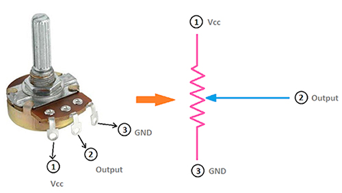
Potentiometer Pinout
A potentiometer typically has three pins, also known as terminals. The pinout of a potentiometer is as follows:
Potentiometer Pinout:
- Terminal 1 (Top Terminal): One end of the resistive track. Connected to one of the outer pins on the potentiometer.
- Terminal 2 (Middle Terminal): The wiper or movable contact that slides along the resistive track. This terminal is connected to the wiper arm, which makes contact with the resistive strip.
- Terminal 3 (Bottom Terminal): The other end of the resistive track. Connected to the other outer pin on the potentiometer.
Common Configurations:
-
For a simple 3-terminal potentiometer with a rotary knob:
- Terminal 1: Connected to one end of the resistive track.
- Terminal 2: Connected to the wiper, which is adjustable.
- Terminal 3: Connected to the other end of the resistive track.
-
For stereo potentiometers (two potentiometers in one unit for stereo applications):
- Terminals 1: Left channel equivalent of Terminal 1.
- Terminals 2: Left channel equivalent of Terminal 2.
- Terminals 3: Left channel equivalent of Terminal 3.
- Terminals 4: Right channel equivalent of Terminal 1.
- Terminals 5: Right channel equivalent of Terminal 2.
- Terminals 6: Right channel equivalent of Terminal 3.
Potentiometer Pinout Summary:
- Terminal 1: One end of the resistive track (Outer pin)
- Terminal 2: Wiper or movable contact (Middle pin)
- Terminal 3: Other end of the resistive track (Outer pin)
The potentiometer pinout allows you to connect the potentiometer in a circuit to adjust resistance and control voltage levels. When wiring a potentiometer, the configuration of the pinout determines how the potentiometer is integrated into the circuit and how the resistance can be varied using the wiper or movable contact connected to the middle terminal.
How Potentiometers are Made?
Potentiometers are variable resistors that are used to adjust electrical resistance in a circuit. The manufacturing process of potentiometers involves several steps to create the resistive track, wiper mechanism, terminals, housing, and assembly. Here is an overview of how potentiometers are typically made:
Manufacturing Process of Potentiometers:
-
Material Preparation:
- The main material used in potentiometers is resistive material, usually a mixture of graphite and ceramic, which provides the desired resistance characteristics.
- Other materials such as metal for terminals, housing components, and wiper mechanisms are also prepared.
-
Forming the Resistive Track:
- The resistive material is mixed and formed into a thin, continuous resistive strip or coating, typically on a ceramic substrate.
- Techniques like silk-screening, deposition, or laser trimming may be used to create the resistive track with precise resistance values.
-
Terminal and Wiper Manufacturing:
- Metal terminals and wiper mechanisms are manufactured separately.
- Terminals are attached to the ends of the resistive track, and the wiper mechanism is designed to move along the resistive strip.
-
Assembly:
- The resistive track with terminals and wiper mechanism is assembled into the potentiometer housing, which is often made of plastic or metal.
- The wiper is attached to a movable mechanism (such as a knob or slider) on the exterior of the potentiometer that allows the user to adjust the resistance.
-
Testing:
- Potentiometers undergo various tests to ensure their electrical properties, such as resistance value, linearity, and reliability.
- Mechanical tests may also be performed to verify the smooth operation and durability of the wiper mechanism.
-
Quality Control and Packaging:
- Potentiometers are inspected for quality control to ensure they meet specifications.
- Once verified, they are packaged according to industry standards for distribution and sale.
Additional Considerations:
- Types of Potentiometers:
- The manufacturing process may vary depending on the type of potentiometer (e.g., rotary, slide, trimmer).
- Automated Manufacturing:
- Some parts of the manufacturing process may be automated to increase efficiency and consistency in production.
- Customization:
- Potentiometers can be customized based on specific requirements, such as resistance values, tolerances, sizes, and features.
By following a series of steps from material preparation to assembly and testing, manufacturers can produce potentiometers that meet the required specifications for use in various electronic devices and equipment.
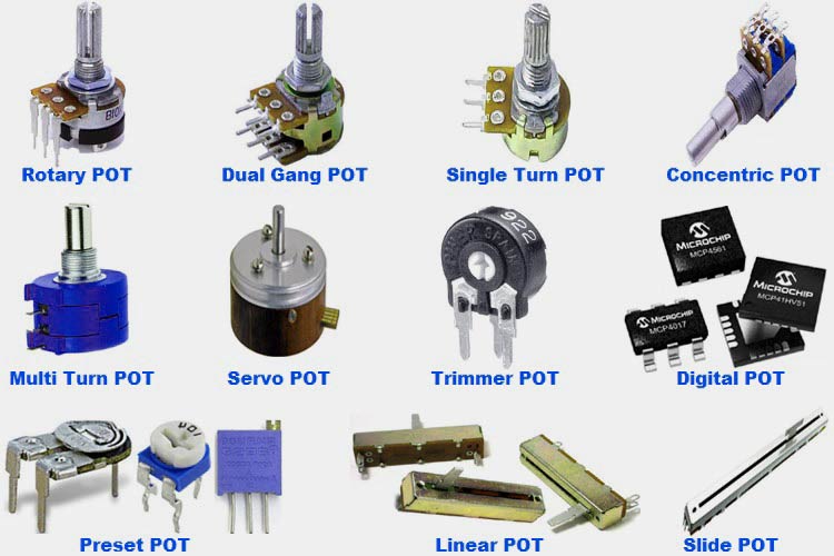
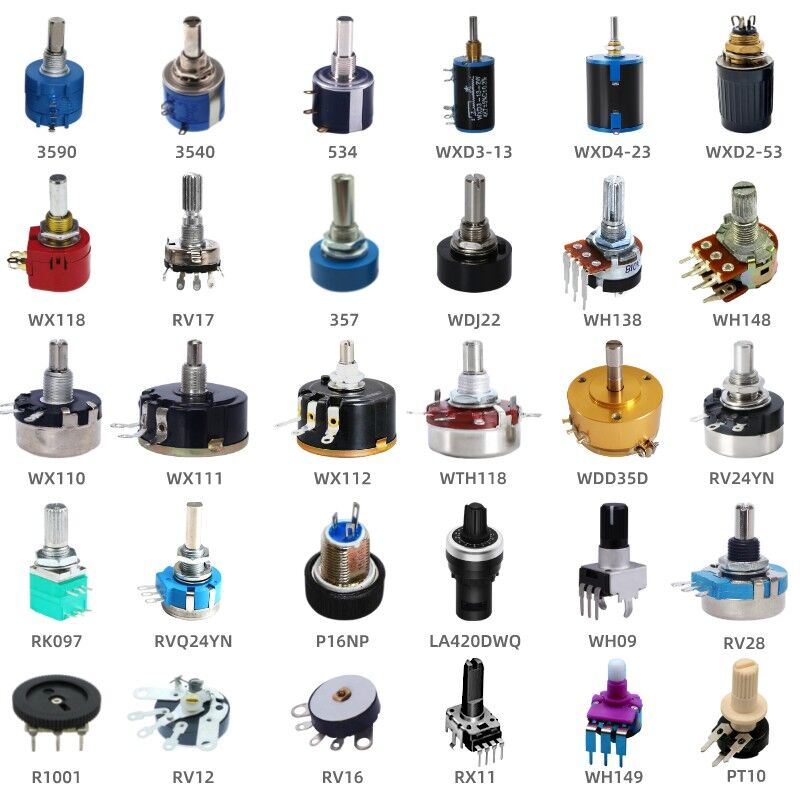
Potentiometer Types
Potentiometers come in various types, each designed for specific applications and requirements. Here are some common types of potentiometers:
1. Linear Potentiometer:
- The resistance changes linearly with the physical position of the wiper.
- Used in applications where a linear change in resistance is required, such as volume control in audio equipment.
2. Logarithmic (Log) Potentiometer:
- Also known as audio taper potentiometers.
- The resistance changes logarithmically with the position of the wiper.
- Commonly used in audio applications where human perception of sound intensity is logarithmic.
- Provides a smoother transition in perceived volume changes.
3. Multi-Turn Potentiometer:
- Requires multiple rotations to change the resistance value.
- Offers finer control and higher resolution compared to single-turn potentiometers.
- Used in precision applications where precise adjustments are necessary, such as calibration instruments.
4. Digital Potentiometer:
- Often referred to as digipots.
- Uses digital signals to control the resistance value electronically.
- Can be controlled using microcontrollers or digital interfaces.
- Suitable for applications where digital control or automation is required.
5. Trimmer Potentiometer:
- Also known as trim pots or trimmer resistors.
- Designed for adjusting and calibrating circuits during manufacturing or servicing.
- Typically small and mounted directly on the circuit board.
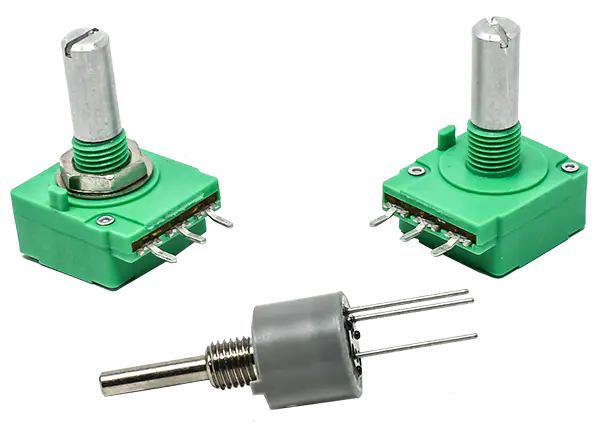
6. Rotary Potentiometer:
- Has a rotary knob or dial for adjusting the resistance.
- Widely used for applications like volume control, lighting control, and motor speed control.
7. Slide Potentiometer:
- Features a sliding wiper mechanism for adjusting the resistance.
- Commonly used in audio mixing consoles, equalizers, and other devices where linear sliding adjustments are required.
8. Motorized Potentiometer:
- Includes a motor for remote or automated adjustment of resistance.
- Suitable for applications where manual adjustment is not practical or rapid and precise adjustments are needed.
9. Touch Potentiometer:
- Operated by touch or proximity sensing.
- Does not require physical contact for adjustment.
- Used in applications where continuous rotation or linear movement is not feasible.
10. Rheostat:
- A two-terminal variable resistor.
- Primarily used to regulate current rather than voltage.
Each type of potentiometer offers unique characteristics and is suitable for specific applications based on factors such as control requirements, precision, form factor, and method of adjustment. Selecting the right type of potentiometer is crucial to ensure optimal performance in electronic circuits and systems.
Potentiometer Wiring Examples
Wiring a potentiometer into a circuit depends on the type of potentiometer and the application it's being used for. Here are a few common wiring examples for different types of potentiometers:
1. Volume Control using a Rotary Potentiometer:
- Components:
- Rotary Potentiometer
- Audio Amplifier
- Wiring:
- Connect one end of the potentiometer to the ground.
- Connect the other end to the input signal.
- Connect the wiper terminal to the amplifier input.
- Adjusting the potentiometer knob changes the volume by varying the resistance.
2. Brightness Control using a Slide Potentiometer:
- Components:
- Slide Potentiometer
- LED or Display
- Wiring:
- Connect one end of the potentiometer to the power supply.
- Connect the other end to the ground.
- Connect the wiper terminal to the LED or display for adjusting brightness.
3. Voltage Divider using a Fixed Potentiometer:
- Components:
- Fixed Potentiometer
- Microcontroller
- Wiring:
- Connect one end of the potentiometer to the power supply.
- Connect the other end to the ground.
- Connect the wiper terminal to an analog input pin on the microcontroller to read varying voltage levels.
4. Trimming Circuit using a Trimmer Potentiometer:
- Components:
- Trimmer Potentiometer
- Circuit Components requiring calibration
- Wiring:
- Connect one end of the potentiometer to a reference voltage.
- Connect the other end to ground or another reference point.
- Adjust the wiper position for fine-tuning the circuit.
5. Automated Potentiometer Control:
- Components:
- Motorized Potentiometer
- Microcontroller or Motor Driver
- Wiring:
- Interface the motorized potentiometer with the motor driver or microcontroller for automated adjustment.
- Control the motor to set the resistance value remotely or automatically based on input signals.
6. Digital Potentiometer Control:
- Components:
- Digital Potentiometer
- Microcontroller or Digital Interface
- Wiring:
- Connect the digital potentiometer to the microcontroller or digital interface for digital control.
- Use digital signals to adjust the resistance value based on program logic or user input.
These wiring examples provide a basic understanding of how potentiometers can be integrated into different circuits for various purposes. The specific wiring configuration will depend on the application, type of potentiometer, and the desired functionality within the circuit.
How to Select a Potentiometer?
Selecting the right potentiometer for your application involves considering various factors such as resistance value, type of potentiometer, tolerance, power rating, size, and mounting options. Here are some steps to help you choose the appropriate potentiometer:
Steps to Select a Potentiometer:
-
Determine Application Requirements:
- Identify the specific application requirements such as voltage or current control, volume adjustment, sensor calibration, etc.
-
Select Potentiometer Type:
- Choose the type of potentiometer based on the application (rotary, slide, trimmer, digital, etc.).
-
Resistance Value:
- Decide on the resistance value required for your application. Ensure the potentiometer's resistance range is suitable for your needs.
-
Tolerance:
- Consider the tolerance required for precision control. Common tolerances are 5%, 10%, or even tighter for more accurate applications.
-
Power Rating:
- Ensure the potentiometer can handle the power dissipation in your circuit. Choose a potentiometer with a power rating higher than the maximum power it will be subjected to.
-
Mounting and Size:
- Consider the physical size and mounting options of the potentiometer to ensure it fits within your application's constraints.
-
Temperature Stability:
- If your application operates in a wide temperature range, consider potentiometers with temperature-stable characteristics.
-
Longevity and Durability:
- Choose potentiometers from reputable manufacturers known for quality and reliability to ensure longevity and stable performance.
-
Environmental Conditions:
- Consider environmental factors such as humidity, vibration, and dust exposure when selecting potentiometers for rugged or outdoor applications.
-
Customization:
- If standard potentiometers do not meet your requirements, explore options for customized potentiometers tailored to your specific needs.
- Budget and Availability:
- Consider the cost of the potentiometer and its availability from suppliers. Ensure it fits within your budget and can be sourced reliably.
- Consult Datasheets:
- Review potentiometer datasheets for detailed specifications, including resistance range, power rating, temperature coefficient, mechanical life, and other relevant information.
By following these steps and considering the key factors mentioned above, you can select the right potentiometer that meets the specific requirements of your circuit or electronic system. If you have further questions or specific requirements, feel free to ask for more detailed guidance.
How to Use a Potentiometer?
Using a potentiometer involves connecting it properly in a circuit and adjusting its position to control a parameter such as volume, brightness, resistance, or voltage. Here's a general guide on how to use a potentiometer effectively:
Steps to Use a Potentiometer:
-
Identify the Potentiometer Connections:
- A potentiometer typically has three terminals: one connected to each end of the resistive track and one connected to the wiper or moving contact.
-
Select the Right Potentiometer:
- Choose a potentiometer suitable for your application in terms of type, resistance value, power rating, and size.
-
Wire the Potentiometer:
- Connect one terminal of the potentiometer to the power supply or ground, another terminal to the input or output signal, and the wiper terminal to the desired component for control.
-
Adjustment Mechanism:
- Depending on the potentiometer type (rotary, slide, digital), use the appropriate adjustment mechanism (knob, slider, digital interface) to change the resistance setting.
-
Functionality:
- Rotate the knob or slide the control to vary the resistance in the circuit. This action will affect the circuit's output, such as changing the volume, brightness, speed, or any parameter controlled by the potentiometer.
-
Observation and Testing:
- Monitor the behavior of the circuit when the potentiometer is adjusted. Check whether the desired parameter is changing according to the potentiometer's position.
-
Fine-Tuning:
- Use the potentiometer to fine-tune circuit parameters for optimal performance. Adjust the potentiometer until you achieve the desired level or setting.
-
Calibration:
- In some applications, potentiometers may be used for calibration purposes. Adjust the potentiometer settings to calibrate sensors, controls, or other components accurately.
-
Safety Precautions:
- Ensure proper electrical safety measures when using potentiometers in circuits. Avoid exposing potentiometers to excessive current or voltage that exceeds their ratings.
-
Experimentation:
- Experiment with different potentiometer settings to understand how they affect the circuit's behavior. This can help you optimize the performance of your system.
Tips for Using Potentiometers Effectively:
- Use the right type of potentiometer for your application.
- Check the datasheet for specifications and ratings.
- Ensure proper wiring and connections.
- Avoid excessive force when adjusting the potentiometer.
- Regularly inspect and clean potentiometers for optimal performance.
By following these steps and tips, you can effectively use potentiometers to control various parameters and customize circuit behavior according to your requirements. If you encounter any issues or need further assistance, don't hesitate to ask for help.