Do you know why stepper motor wires have different colors and what different colors stand for? Understanding the meaning of stepper motor wire colors is essential for beginners delving into the world of motor control.
What's The Meaning of Stepper Motor Wire Color Code
Stepper motors are commonly used in various applications to control precise movement. The wire color code for stepper motors can vary depending on the manufacturer and the specific model of the motor. However, there are some common standards that are typically used to identify the wires of a stepper motor. Here is a general guideline for interpreting the wire color code of a stepper motor:
- Bipolar Stepper Motor:
- 4-Wire Configuration:
- Typical Color Code:
- A+, A-, B+, B-
- Interpretation:
- A+ and A- are typically one coil pair.
- B+ and B- are typically another coil pair.
- Typical Color Code:
- 6-Wire Configuration:
- Typical Color Code:
- A+, A-, B+, B-, C+, C-
- Interpretation:
- A+, A-, B+, B-, C+, C- are three separate coil pairs.
- Connecting A+ to A- powers one coil, while connecting B+ to B- powers another coil, and so on.
- Typical Color Code:
- 4-Wire Configuration:
- Unipolar Stepper Motor:
- 5-Wire Configuration:
- Typical Color Code:
- Center Tap (common), Coil A, Coil B, Coil C, Coil D
- Interpretation:
- Center Tap (common) is usually the center connection for each coil pair.
- Coil A, Coil B, Coil C, and Coil D are separate coil windings.
- Typical Color Code:
- 5-Wire Configuration:
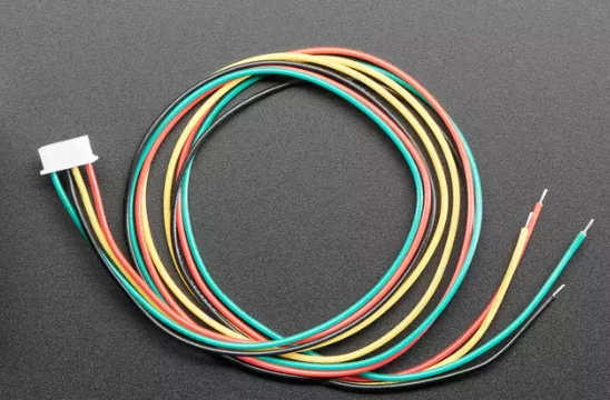
- Color Codes:
- Common Colors:
- Black (or Blue): A or Coil 1
- Green: A- or Coil 1-
- Red: B or Coil 2
- Yellow: B- or Coil 2-
- Common Colors:
Note: It is crucial to refer to the datasheet or documentation provided by the stepper motor manufacturer for specific details on the wire color code for your particular motor model. Incorrectly wiring a stepper motor can lead to malfunction or damage to the motor or your control system.
When working with stepper motors and interpreting the wire color code, following the manufacturer's guidelines and understanding the wiring configuration is essential to ensure proper operation of the motor and your control system.
Category of Stepper Motor Wire Colors
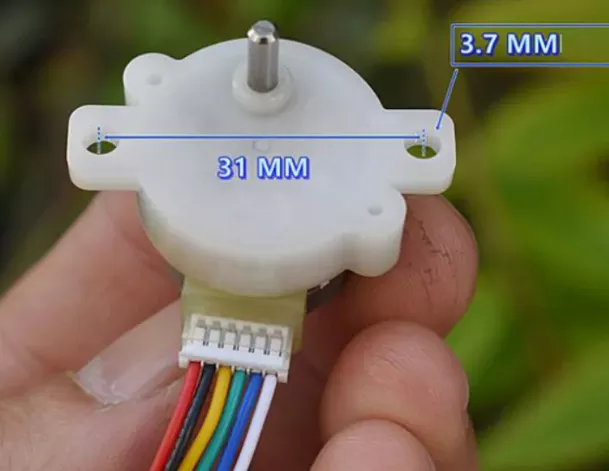
Stepper motors typically have wires of different colors to help identify and distinguish the various coils within the motor. The wire colors in a stepper motor system can be categorized based on their functions or connections. Here are the common categories of stepper motor wire colors:
1. Coil Pair Wires:
2. Common Wire:
3. Direction Control Wires:
4. Coil Excitation Phases:
5. Common Ground Wire:
6. Power Supply Wires:
7. Feedback or Sensor Wires:
8. Control Signal Wires:
Understanding the categories of stepper motor wire colors can help in correctly identifying and connecting the wires during motor installation and setup. Always refer to the manufacturer's datasheet or documentation for specific information on wire colors in your stepper motor system.
Why Do You Need to Understand Stepper Motor Wire Colors
Understanding stepper motor wire colors is crucial for several reasons:
-
Proper Connection: Knowing the wire colors helps you correctly connect the stepper motor to the driver or controller, ensuring that the motor operates as intended. Incorrect connections can lead to motor malfunction or damage.
-
Coil Identification: Different wire colors correspond to specific coils within the stepper motor. By understanding these colors, you can identify and energize the coils in the correct sequence for smooth motor operation.
-
Direction Control: Some wire colors determine the direction of rotation for the stepper motor. Understanding these colors allows you to control the motor's rotation direction effectively.
-
Troubleshooting: When diagnosing issues or performing maintenance on the stepper motor system, knowing the wire colors helps in troubleshooting any wiring problems or connectivity issues that may arise.
-
Compatibility: Understanding stepper motor wire colors ensures you select compatible drivers, controllers, and power supplies for the motor. This knowledge is essential for integrating the motor into your system successfully.
-
Safety: Properly connecting stepper motor wires based on their colors reduces the risk of electrical shorts, overheating, or other safety hazards that may occur due to incorrect wiring.
-
Efficiency: Correctly wiring a stepper motor based on wire colors ensures optimal performance and efficiency of the motor system, preventing unnecessary wear and tear on the components.
-
Flexibility: Knowledge of stepper motor wire colors allows you to work with a variety of stepper motors and control systems, enabling flexibility in system design and implementation.
-
Preventing Damage: Incorrectly wiring a stepper motor due to a lack of understanding of wire colors can lead to irreversible damage to the motor, driver, or associated electronics. Understanding wire colors helps prevent such damage.
By understanding stepper motor wire colors, you can ensure proper installation, operation, and maintenance of stepper motor systems. This knowledge is essential for effective control, troubleshooting, and optimization of stepper motor performance in various applications.
4/6/8-Wire Stepper Motor Wiring Diagram You Might Need
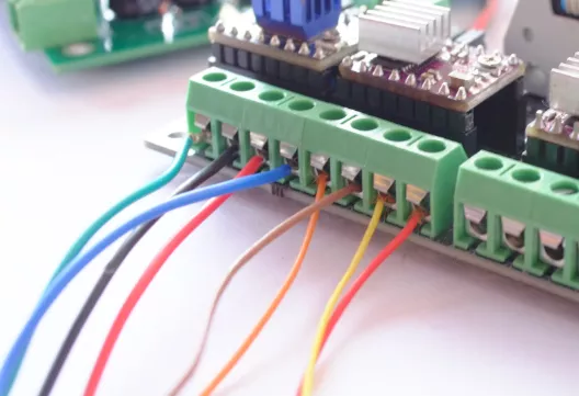
For a 4-wire, 6-wire, or 8-wire stepper motor, the wiring configuration can vary based on the motor type and manufacturer. Below, you will find a generalized wiring diagram for each type of stepper motor to provide you with an idea of how these motors can be connected:
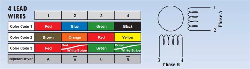
4-Wire Stepper Motor Wiring Diagram:
- Wire Colors: A+, A-, B+, B-
- Wiring:
- Connect A+ and A- to one coil.
- Connect B+ and B- to another coil.
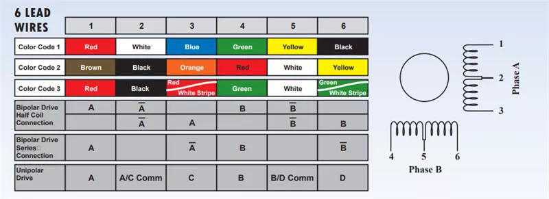
6-Wire Stepper Motor Wiring Diagram:
- Wire Colors: A+, A-, B+, B-, C+, C-
- Wiring:
- Connect A+ and A- to the first coil.
- Connect B+ and B- to the second coil.
- Connect C+ and C- to the third coil.
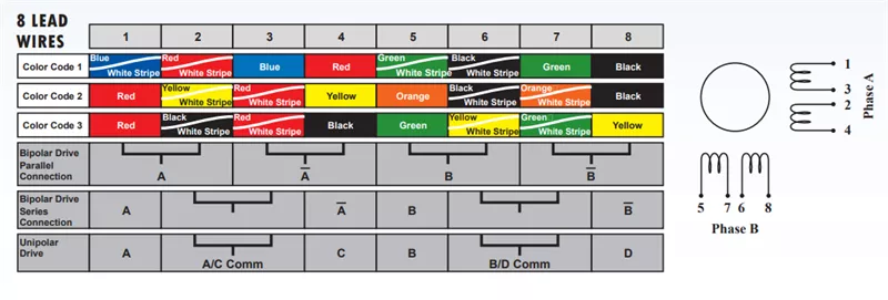
8-Wire Stepper Motor Wiring Diagram:
- Wire Colors: A1+, A1-, B1+, B1-, A2+, A2-, B2+, B2-
- Wiring (Parallel/Series):
- Parallel: Connect A1+ to A2+ and A1- to A2- for each pair, then connect the pairs.
- Series: Connect A1+ to A1- for one coil and B1+ to B1- for another coil. Repeat for the second pair.
These diagrams offer a general idea of how to wire 4, 6, and 8-wire stepper motors. However, for specific models and configurations, always refer to the manufacturer's datasheet or documentation to ensure accurate wiring for optimal performance and functionality.
What happens if you wire a stepper motor incorrectly?
Wiring a stepper motor incorrectly can lead to various issues that can affect the motor's performance, functionality, and can even cause damage to the motor itself or other components in the system. Here are some common consequences of incorrectly wiring a stepper motor:
-
Motor Malfunction: Incorrectly wiring a stepper motor can lead to the motor not functioning as intended. The motor may not rotate in the correct sequence, direction, or may not move at all.
-
Overheating: Incorrect wiring can cause excessive current to flow through the motor coils, leading to overheating. This can damage the coils, insulation, or other internal components of the motor.
-
Reduced Torque or Power Output: Improper wiring can result in reduced torque or power output from the stepper motor. This can impact the motor's ability to move loads or perform tasks efficiently.
-
Noise and Vibrations: Incorrect wiring may cause the motor to produce abnormal noise or vibrations during operation. This can be a result of the motor not receiving the proper signals to move smoothly.
-
Driver Damage: Incorrect wiring can damage the motor driver or controller. The driver may not be able to deliver the correct signals to the motor, leading to potential failure of the driver circuitry.
-
Motor Damage: Continuously running a stepper motor with incorrect wiring can cause damage to the motor coils, magnets, or other internal components. This can lead to permanent motor damage and require replacement.
-
Safety Risks: Incorrectly wiring a stepper motor can create safety hazards such as short circuits, electrical shocks, or fires. It is essential to ensure proper wiring to maintain a safe working environment.
-
System Failure: In a larger system where the stepper motor is a part of a complex setup, incorrect wiring can lead to overall system failure. This can impact the performance of other connected components and devices.
To avoid these consequences, it is important to carefully follow the manufacturer's wiring guidelines provided in the datasheet or documentation. Double-checking the wiring connections before powering on the stepper motor is essential to prevent damage and ensure proper functionality. If unsure about the correct wiring configuration, it is advisable to seek assistance from someone with experience in stepper motor wiring or consult a professional technician.