What is a circular connector?
Circular connectors are cylindrical electrical devices of varying sizes with round mating surfaces. They contain multiple pins, or contacts, that connect to applicable components to transmit power, signals, or data. They may also be called circular interconnections. Internal contacts mate with wires or cables to carry signals.
Their cylindrical or tubular bodies make these connectors particularly rugged, resistant to vibration and shock damage, extreme temperatures and pressures, external signals or interference, and the intrusion of dust or gases.
Modern products currently available in this category range from simple plastic, metal or composite standard circular connectors to many other types including DIN, metric, sealed, push-pull, keyed, mixed-signal and micron or nano versions. Hybrid options are available to combine power, signal and data into a single device. Modular or custom solutions can also be found where connector products are customized for specific applications.
Characteristics of circular connectors
Their tubular or cylindrical shape gives circular connectors a higher strength-to-weight ratio than any other shape. This inherent strength resists external factors, impact damage and accidental decoupling. This strength also makes them useful and resilient in applications that require frequent plugging and unplugging. The number of internal pins or contacts varies depending on the application, and the layout of the contacts or internal keys ensures proper alignment and insertion of the mating device.
Circular connectors are most often (but not always) connected via a threaded area on the housing. This screw-in connection allows them to lock into place easily and securely and stay in place despite vibration or shock. Other types of connection systems include bayonet locks, push/pull locks, and spring locks.
The basic structure of a circular connector includes the following:
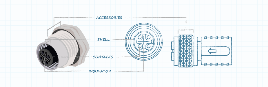
Basic structure of female circular connector
● Contacts - These are the pins and sockets located inside the connector that mate to form an electrical connection. The contact pair consists of a male contact pin and a female socket.
● Insulator - This is the material used to encapsulate the contacts and insulate them from each other and from the connector housing. This material also holds the contacts in the correct location in the housing and keeps them properly spaced from each other.
● Housing – This is the housing of the connector that houses the contacts and insulator. It also provides alignment when the connector halves are mated and secures the connector parts to each other or to the device.
● Accessories – These are additional components used to position, guide, clamp, secure or seal connector components. They include pins, rings, keys, clips, washers, etc.
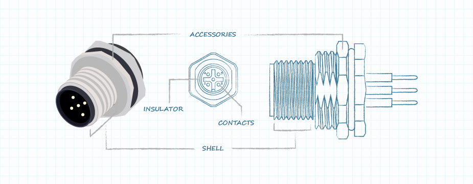
Basic structure of male circular connector
Wide range of uses for circular connectors
Due to their high performance with respect to extreme vibration, shock, temperature, pressure and interference (EMI and RFI), circular connectors are increasingly used in many industrial applications requiring power transmission, signal transmission, data transmission and mixed signal transmission. Multiple uses (power + signal + data). They are best used when a robust connector construction is required, ingress protection is required, a secure mating system is required, or protection against EMI or RFI is required.
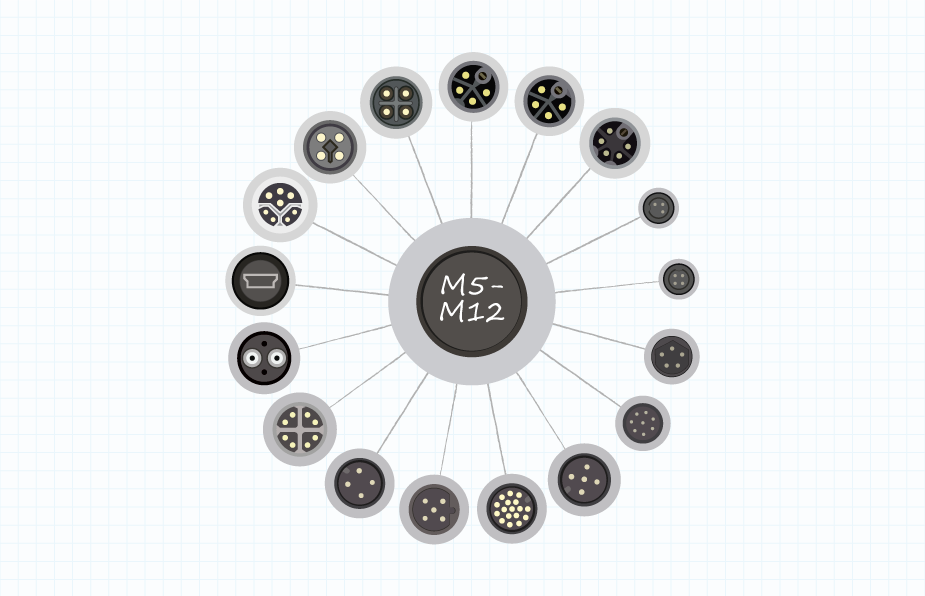
M5, M8, M12 designations and codes
Type M circular connectors are a range of standard product types used to connect sensors and actuators in industrial network applications. They are designed to operate in extreme conditions. The "M" designation refers to the metric thread size on the connecting nut and mating socket, which is the relative size of the connector. M5 connectors have 5 mm diameter fasteners, M8 has 8 mm diameter fasteners, and M12 has 12 mm diameter fasteners.
Circular connectors and cables are further divided into other categories based on the keying or shape of the contact body. Various codes ensure that the cable is installed with the correct connector. The different codes used and their definitions are as follows:
● A – Connectors for sensors, DC power, and 1 Gbit Ethernet (a protocol used to connect computer systems to form a network).
● B – Connector for Fieldbus (an industrial computer network used for distributed control) and Profibus (a digital network standard that provides communication between field sensors and control systems).
● C – Connector with double keyway for enhanced safety, for AC power to sensors and actuators.
● D – Connector for 100 Mbit Ethernet and Profinet (protocol for data exchange between controller and device) systems.
● X – Connector for 10 Gbit Ethernet high-speed applications and Power over Ethernet (PoE).
● S – AC power connector (replaces C – coded part).
● T – DC power connector (replaces A – coded part).
Different circular connector categories and connection types
Applicable standards for circular connectors
Circular connectors are designed and manufactured to comply with several different national and international standards organizations. The following are some of the standards bodies and names relevant to the development and continued use of these products:
● UL – Underwriters Laboratories standards related to circular connectors (UL1977 and UL2238) cover safety issues and properties of materials used in manufacturing.
● IEC – International Electrotechnical Commission standards define and describe several types of circular connectors, including IEC 61076-2-113, which defines requirements for M12 connectors.
● MIL/AERO – The military standard for circular connectors was developed by the U.S. Department of Defense in the 1930s and covers the design and testing requirements for a variety of connectors, including circular devices.
● EN – European Standard (European Norm) covering circular connector details in EN-IEC 61076. Other standards cover connector specifications by application.
● IP – Ingress protection class is defined by the IEC 60529 standard and covers protection against solids and liquids entering the connector body. ANSI 60529 covers IP in the United States and EN 60529 covers IP in Europe.
● DIN – The German National Standards Organization (Deutsches Institut Fur Normung) standard covers circular connectors, specifically those in DIN 41524 and other documents.
● VARAN – Versatile Automation Random Access Network is an Ethernet-based bus system implemented in machine automation hardware, including circular connectors.
Circular connector selection criteria
When you specify circular connectors for a new design or redesign, there are many criteria to consider. The first is whether your design requires a circular plastic connector (CPC) or a circular metal shell connector (CMC). Beyond that, here's a non-exhaustive list of parameters (in random order) for you to decide:
● Category (Male/Female): The male part contains the contacts that plug into the socket or the socket of the female part. Most plugs and sockets are designed to fit within their own brand or manufactured product line. Typically, connectors from different manufacturers are not interconnected. You will usually purchase connectors in mated form, but not always.
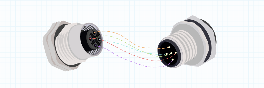
Circular connector male and female mating
● Number of Contacts: The number of conductive pins or contacts your design requires in the connector to carry the signals, data, or power you need to move.
● Termination: This is how a wire or cable mates with conductive contacts in a connector. Some options include soldering, wire wrapping, lugs, or crimping.
● Contact size: The diameter of each contact, or the size of wire that can mate with each contact.
● Voltage and current ratings: The maximum voltage or current that a connector is designed to carry. The ampere rating is the flow of electrical current, expressed in amperes (A). Rated voltage is the amount of voltage that can be safely carried, expressed in volts (V).
● Insertion frequency: The regularity with which a connector is connected and disconnected (also known as the plug-and-unplug cycle). Frequent mating and unmating may require stronger connectors or cable protection accessories.
● Installation type: How the connector is installed, including cable installation, panel installation, or circuit board installation. Different mounting hardware is available for each type.
● Coupling or locking style: How securely the connector mates. Locking methods include bayonet, latch, push-pull, threaded and quick-disconnect.
● Backshell type: The connector backshell threads onto the cable side of the circular connector to provide secure cable support. There are several different types of backshells available, including straight, right-angle, pigtail, spring-loaded, strain relief, sealed, and crimped.
● Environmental factors: Will the connector be exposed to liquids, gases, or immersion? Do connectors require protection from EMI or RFI signals? Will the connector be exposed to corrosive chemicals, excessive vibration, or frequent impacts? The answers to each question will help determine the quality, features and accessories you may need.
● Materials used: The connector body can be stainless steel, aluminum, plastic, composite or brass, depending on your requirements and budget.
● Accessories: Connector manufacturers offer many different types of accessories to enhance the functionality of their products. The list of these is long, but some examples include seals, jackets and covers to lock out liquids and gases, strain reliefs and cable clamps to protect cable disconnections, back shells to protect connections, mounting flanges, gaskets and grommets, and cable clamps for easier insertion/removal.
● Plugs and receptacles: Although industry standards vary, generally receptacles and jacks are associated with panel-mount connectors, while plugs are connectors that are part of a cable assembly. Again, there is no standard convention for this naming, so different manufacturers may use alternative terms.
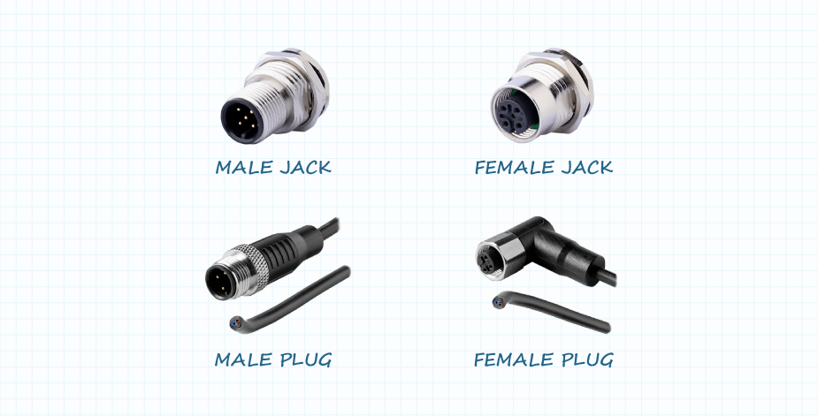
Gender jacks and plugs
Applications
Since their introduction into military applications in the 1930s, the uses of circular connectors have continued to expand. For example, today's process control systems and factory floor sensor networks are often found in harsh environments, requiring interconnected products to operate reliably under challenging conditions.
Electronic medical equipment also uses circular connectors to ensure that hospital staff always connect cables correctly and do not loosen them when moving patients. Many other application areas that enjoy the benefits of connecting using circular connectors include:
● Process control and industrial automation
● Factory wiring
● Transportation
● Aerospace and Defense
● Medical equipment
● Robotics
● Audio/video communication
● Radio and television communications
● Vitality
● Drone
● Test and Measurement
generalize
Circular connectors have been used for many years and have proven themselves to be reliable components that can perform in a variety of harsh environments. CUI Devices offers a variety of circular connectors and cables to meet the challenges of nearly any application.